Manchester Encoding/Decoding
The X2010 FM Transceiver used in this project only works with AC data signals, thus all data must be manchester encoded by the microprocessor prior to transmission. Synchronous encoding in general also has its advantages, such as being able to receieve at different data rates by calculating the frequency of the preamble.
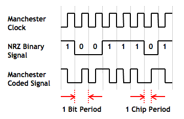
In Manchester encoded data, the NRZ binary signal is XOR'ed with a 50% duty cycle clock running at twice the data rate (Figure 1). As a result, a '1' is encoded to a '10', and a '0' is encoded to a '01'. The resulting bits are called 'chips'.
|
| Figure 1: Manchester Encoded Signal |
The previously used Manchester encoding and decoding algorithms had several flaws, including succeptibility to phase drift, low tolerance to clock rate error, unreliable synchronisation, and poor performance. Both algorithms have been reveloped using a different approach, resulting in significant perfomance improvements.
Back To Top
Manchester Encoding Algorithm
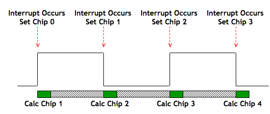
Previously, the output was cacluated and set all in the one step, making the phase of the signal dependent on the time taken to calculate the output value. In the new Manchester encoding algorithm, each change of the output is calculated in advance and scheduled using a capture/compare interrupt (Figure 2). As a result, any possibility of phase drift is completely eliminated.
|
| Figure 2: Manchester Encoded Signal |
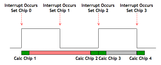
This technique also allows for "processing slack" in the system, which enables the entire encoding algorithm to be run under interrupt, freeing up the microprocessor's spare cycles for other tasks. Consider that a data fetching operation occurs between the calculation of chip 1 and chip 2 (Figure 3). As long as the calculations for chip 2 are complete before it is scheduled to be set, the output is not affected.
|
| Figure 3: Processing Slack |
Back To Top
Manchester Decoding Algorithm
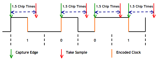
The previous Manchester decoding algorithm relied on start/stop bits, which incurred a 25% bandwidth overhead, and could not synchronise quickly or reliably. The new Manchester decoding algorithm is based on an existing technique, which synchronises to the clock encoded in the signal, and will correctly acquire the clock as soon as the data bit value changes (Figure 4).
|
| Figure 4: Manchester Decoding |
The algorithm can be summarised as follows:
- Wait for an edge (of either polarity).
- Wait 1.5 chip periods.
- Take a sample.
- Rinse, lather, and repeat.
Note in Figure 4 that even if an incorrect edge is detected as the clock, the correct edge will be acquired as soon as the data bit changes from a 1 to a 0 (or vice versa).
Apart from eliminating the 25% bandwidth overhead of the start/stop bits, and quick and reliable synchronisation, the new algorithm is much more efficient - Whereas the previous decoding algorithm limited the speed of the system to 2.4 kbps, the new algorithm has been tested and shown to work at 9.6 kbps. Faster data rates mean less utilization of the medium, leading to lower power consumption, and less chance of collisions. For this project, the data rate was set at 5 kbps, and the microprocessor powered down during the spare instruction cycles to save power.
Back To Top
Clock Detection
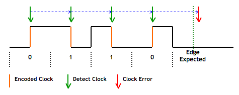
Due to the relatively poor signal-to-noise ratios in remote ad hoc sensor networks, the carrier detect (CD) and recieved signal strength indicator (RSSI) functions of the transceiver cannot always be relied upon to determine if a valid signal is present. As an alternative, an algorithm was developed which detects whether a valid clock signal is present. It works by verifying that the delay between clock edges is no more than 1 clock period, (2 chip periods).
|
| Figure 5: Clock Detect Mechanism |
The algorithm can be summarised as follows:
- Every time a clock edge is detected, a 'clock watchdog timer' is set to go off in 1.1 clock periods.
- If another clock edge is detected before 1.1 clock periods have elapsed, the timer is reset and nothing happens. This allows for a 10% clock rate error.
- If no clock edge is detected before 1.1 clock periods have elapsed, the timer goes off, indicating that the clock signal has been lost.
Back To Top
