The some-thing's connected to the some-thing...

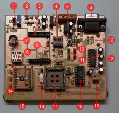
The hardware platform is based on the Microchip PIC18C452 microcontroller. An FM Transceiver and a Variable Gain RF Amplifier provide programmable output power, which is required for the Power Aware Routing Optimisations (PARO) developed by Steven Sloots in 2004. External RAM is required to cache Dynamic Source Routing (DSR) routing information. A real time clock is required to accurately time long sleep intervals.

Please click on each component in the following block diagram to learn about it:

Hardware Block Diagram Real Time Clock External RAM Wideband CMOS Switch Variable Gain RF Amp FM Transceiver PIC Microcontroller
In case clicking on the diagram doesn't work:
PIC Microcontroller | Real Time Clock | External RAM | FM Transceiver | Variable Gain RF Amp | Wideband CMOS Switch

Back To Top

Honey, I shrunk the bypass relay

2004 Hardware
Hardware from Steven Sloot's 2004 Thesis Project

Because the transceiver only has one antenna connection, the RF amplifier must be bypassed to allow reception. The antenna is normally connected directly to the transceiver, and during transmission it is connected directly to the ouptut of the amplifier (refer to the block diagram).

This was previoulsy achieved using a bypass relay, as shown in the adjacent figure (the big square red thing). The relay requires 500mA to operate, which incurs a significant power consumption overhead for transmission. In the new version of the hardware, it has been replaced with a wideband CMOS switch, which only requires 5uA to operate - a staggering power saving.

Back To Top

And Bob's yer uncle...

2004 Hardware
  1. Emitter follower voltage source for ADG918.
  2. Power LED.
  3. IC Socket for X2010 FM Transceiver
  4. Communications isolation / external
    connection header.
  5. Power connector.
  6. RS-232 interface.
  7. 50Ω BNC Connector for External Antenna.
  8. ADG918 Wideband CMOS Switch (on carrier board).
  9. RSSI low pass RC network.
  10. Reset switch and slow power-on reset circuit.
  11. Indicator LEDs.
  12. RJ12 connector for MPLAB ICD2
    (not installed).
  13. MAX232 level shifter.
  14. Power track (note the extra thickness).
  15. AD8369 Variable Gain RF Amplifier.
  16. External 4Mhz crystal oscillator.
  17. 44-pin PLCC socket for MPLAB® ICE2000.
  18. DS1305 Real Time Clock.
  19. FM25C160 External Memory.
PCB Revision 3, as constructed
 

Back To Top

Links

Back To Top